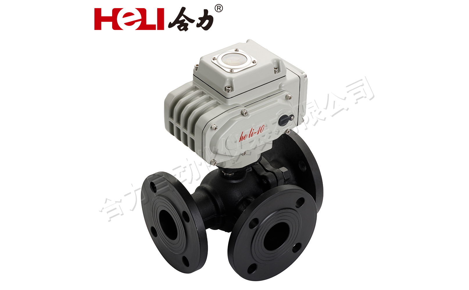
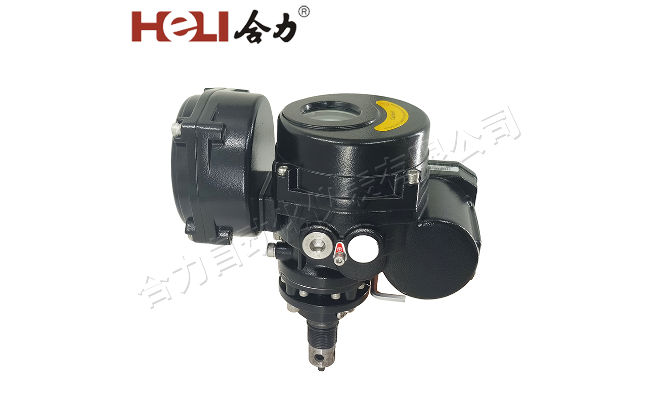
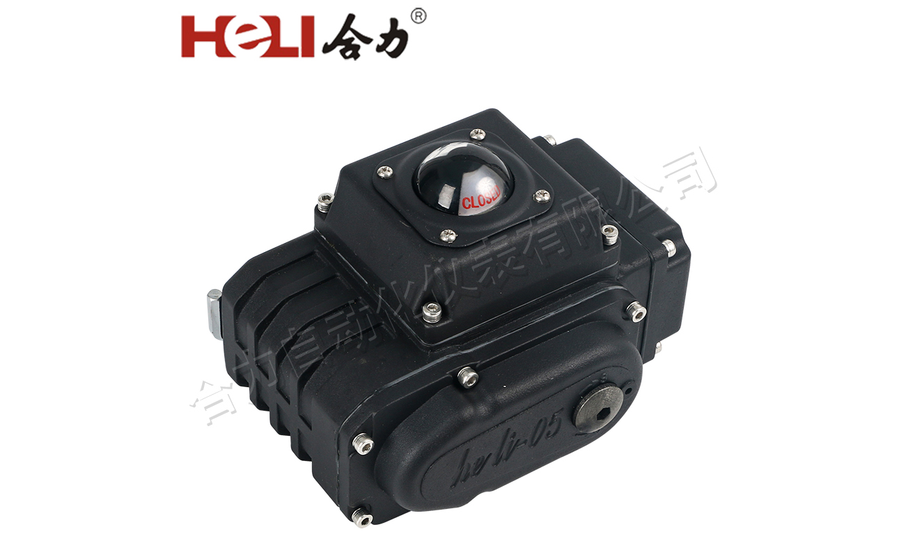
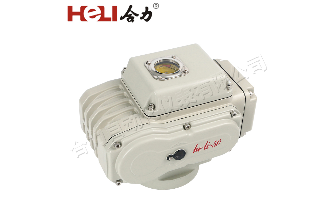
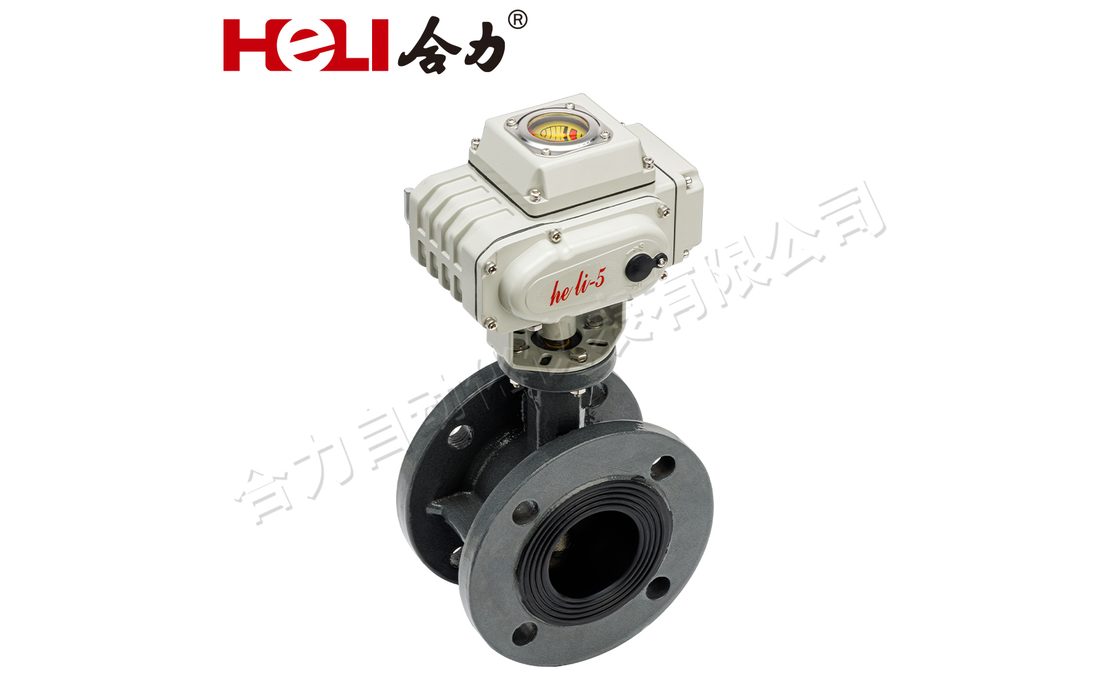
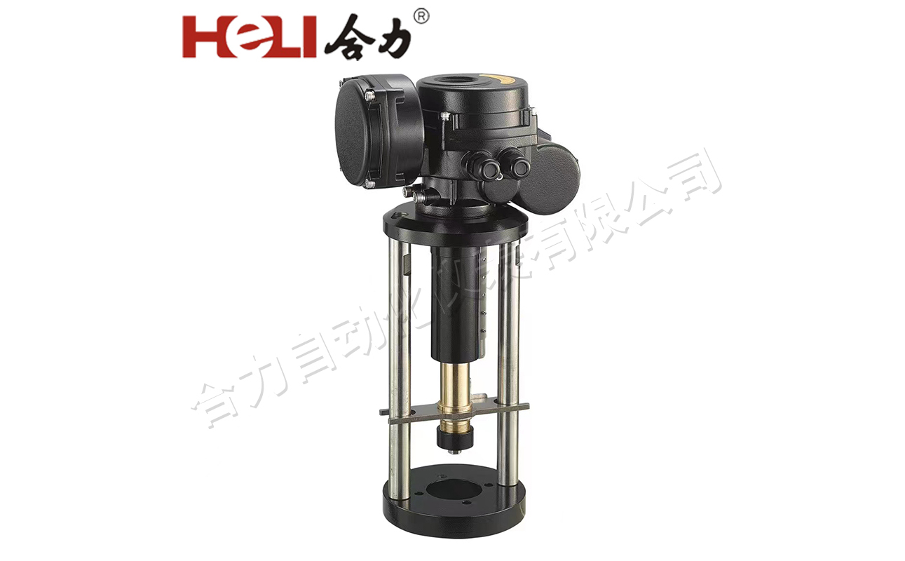
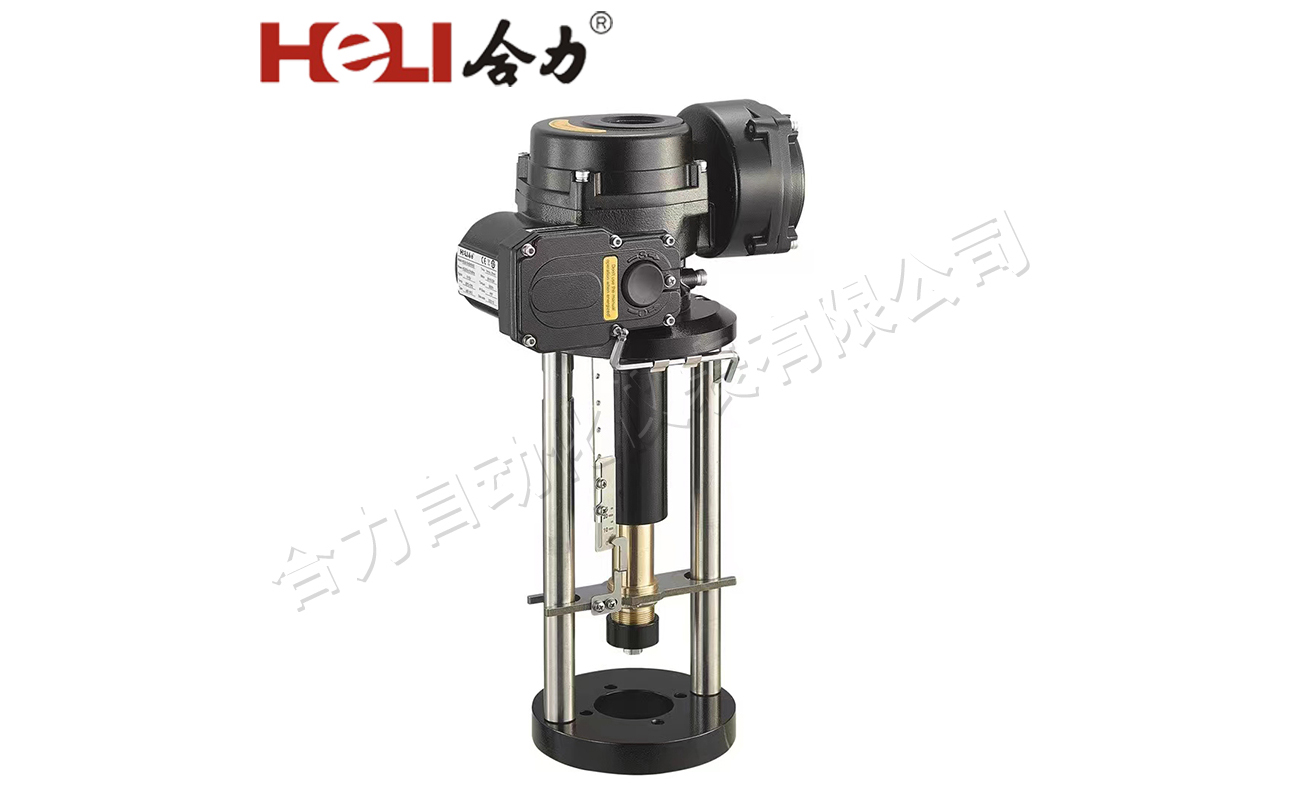
Los actuadores eléctricos de válvula lineal de la serie HEQ B son el derivado de los productos de la serie HEQ de nuestra empresa. Tiene las características de estructura compacta, rendimiento confiable, fácil de operar, etc., adecuados para válvulas de torsión pequeñas y de diámetro pequeño. Esta serie de productos es dividido en tipo a prueba de explosiones y tipo no ex.
Descripción del producto
Los actuadores eléctricos de válvula lineal de la serie HEQ B son el derivado de los productos de la serie HEQ de nuestra empresa. Tiene las características de estructura compacta, rendimiento confiable, fácil de operar, etc., adecuados para válvulas de torsión pequeñas y de diámetro pequeño. Esta serie de productos es dividido en tipo a prueba de explosiones y tipo no ex.
El actuador eléctrico de válvula a prueba de explosiones cumple con GB/T3836.1-2021, GB/T3836.2-2021, GB/T3836.31-2021, marcas a prueba de explosiones: Ex db IIC T6 Gb.Ex tb IIIC T80 ℃ Db.
Especificación de tipo (Tipo B)
Ambiente de trabajo
Fuente de alimentación (opcional)
Trifásico: AC380V, AC415V, AC440V; ±10% 50/60Hz
Monofásico: AC110V, AC220V;±10% 50/60Hz;
CC 24 V ± 10 %
Precisión de ajuste ±1%.
Configuración de posición de pérdida de señal:"hold","full off",'full on"3 opcional.
Temperatura ambiente: (tipo a prueba de explosiones) -25~50 C, (tipo no a prueba de explosiones) -25 ~ 70 C; Humedad relativa ambiental no superior al 90 % (25 ℃).
Servicio de trabajo: 1200 veces/h S4-40%.
Especificación de tipo (Tipo B)
(1) Caja eléctrica modulante (2)Cubierta de la caja (3) Gusano (4)Motor (5) Tablero de calificación (6)Tornillo de accionamiento de desplazamiento (7)Escala (8) Tuerca de cobre de transmisión (9)Puntero (10) Resorte de disco (11)Manguito de conexión (con vástago de válvula) (12) Pasador de soporte (13) Brida (con válvula) conexión de plataforma) (14)Cubierta manual (15)Conector de cable 2 piezas M20*1,5 | ![]() |
Product Dimension
Size | A | B | B1 | B2 | C | D | D1 | D2 | n-d4 | E | F | L | H | P | M1 |
Model | |||||||||||||||
HEQ2-03 | 468 | 182 | 131 | 120 | 95 | 155 | 80 | 60 | 4-Φ10 | 24 | 156 | 120 | 25 | 24 | M10 |
HEQ2-04 | 468 | 182 | 131 | 120 | 95 | 155 | 80 | 60 | 4-Φ10 | 24 | 156 | 120 | 25 | 24 | M10 |
HEQ3-06 | 535 | 255 | 171 | 131 | 130 | 159 | 105 | 80 | 4-Φ12 | 24 | 201 | 120 | 25 | 24 | M12*1.25 |
HEQ3-10 | 615 | 255 | 171 | 131 | 140 | 159 | 118 | 95 | 4-Φ14 | 24 | 201 | 120 | 25 | 24 | M16*1.5 |
HEQ3-16 | 650 | 255 | 171 | 131 | 175 | 159 | 130 | 100 | 4-Φ18 | 24 | 201 | 120 | 25 | 24 | M20*1.5 |
HEQ3-20 | 650 | 255 | 171 | 131 | 175 | 159 | 130 | 100 | 4-Φ18 | 24 | 201 | 120 | 25 | 24 | M20*1.5 |
Technical Parameter
Parameter | Output thrust (N) | Running time (mm/s) | Moter power (W) | Stroke (mm) | Rated Current(A) | Weight (Kg) | |||
Model | AC380V | AC220V | AC110V | DC24V | |||||
HEQ2-03 | 3000 | 1.0 | 25W | ≤40 | 0.13A | 0.32A | 0.55A | 2.1A | 16 |
HEQ2-04 | 4000 | 30W | 0.17A | 0.37A | 0.71A | 2.7A | |||
HEQ3-06 | 6000 | 1.2 | 60W | 0.25A | 0.5A | 1.0A | 6.8A | 25.9 | |
HEQ3-10 | 10000 | 90W | 0.38A | 0.75A | 1.5A | -- | |||
HEQ3-16 | 16000 | 0.83 | 90W | 0.38A | 0.75A | 1.5A | -- | 26.3 | |
HEQ3-20 | 20000 | 120W | 0.55A | 1.1A | 2.3A | -- |
Note:The product is equipped with modulating electrical box weight plus 1kg.
Wiring Drawing
![]() | B1K4:Base on/off type(single phase) |
Terminal wiring description: 1、terminal 1 connected to the power supply neutral line: 2、When the power phase line and terminal 2 are connected, the operation is "on", and the operation stops after the stroke switch 0LS, while terminal 2 and terminal 4 are connected: 3、When the power phase line and terminal 3 are connected, the operation is "off',and stops after the CLS action of the stroke switch,while terminal 3 and terminal 5 are connected;: 4、Terminal 7 is the common end of passive signal contact, "on'operation in place with terminal 8,'off"operation in place with terminal 9 connected;: 5、Terminal 10 is the wiring end of the heating dehumidifier.Can not use two or more electric devices in parallel,otherwise the switch may not be in place or the motor overheating phenomenon |
![]() | B1K2:Base on/off type(three phase) |
Terminal wiring description: 1、terminals 1,2,3 connected to the threephase power supply after the inverter circuit; 2、Terminal 4 is the common end of the control circuit; 3、Terminal 5 is 'open"operation control,to the stroke switch OLS action,terminal 5 and terminal 4 disconnect; 4、Terminal 6 is "off'operation control,when the stroke switch CLS action,terminal 6 and terminal 4 disconnect; 5、Terminal 7 is the common end of the passive signal contact,and the 'on"operation is connected with terminal 8,and the "off"operation is connected with terminal 9; 6、Terminal 10 is the wiring end of the heating dehumidifier. |
![]() | B1K4:Base on/off type(DC power) |
Terminal wiring description: 1、When terminal 1 is connected to the positive terminal of the power supply and terminal 2 is connected to the negative terminal of the power supply,run in the "on' direction and stop when the travel switch OLS is activated. At the same time,terminal 1 and terminal 3 are connected; 2、when terminal 1 is connected to the negative terminal of the power supply,terminal 2 is connected to the positive terminal of the power supply,the "off direction of operation,until the stroke switch CLS action stops,and terminal 2 and terminal 4 are connected; 3、Terminal 7 is the common end of the passive signal contact,and the 'on'operation is connected with terminal 8,and the "off"operation is connected with terminal 9; 4、Terminals 9 and 10 are the wiring ends of the heating dehumidifier. |
![]() | B2K9(B2K8):Basic Modulating (single-phase power) |
Terminal wiring description: 1、terminal 1,2 connected to the power supply eutral line, phase line; 2、input control signal "+"connect terminal 6,'-'connect terminal 7; 3、output feedback signal "+" connect terminal 8,"-" connect terminal 9; 4、Terminal 3 is the common end of the passive signal contact,and the 'on'operation is connected with terminal 5、Terminal 10 is the wiring end of the heating dehumidifier. |
![]() | B1K9:Position transmitter (single phase power supply) |
Terminal wiring description: 1、terminal 1,2 connected to the power supply neutral line, phase line: 2、When the power phase line and terminal 6 are connected,the operation is "on",and the operation stops after the stroke switch 0LS: 3、When the power phase line and terminal 7 are connected,the operation is "off",and the operation stops after the stroke switch CLS is activated; 4、output feedback signal "+connect terminal 8,"-"connect terminal 9: 5、Terminal 7 is the common end of the passive signal contact. and the "on"operation is connected with terminal 8.and the "off" operation is connected with terminal 9: 6、Terminal 10 is the wiring end of the heating dehumidifier. |
![]() | B1K5:Position transmitter (single phase power supply) |
Terminal wiring description: 1、terminal 1 connected to the power supply neutral line; 2、When the power phase line and terminal 2 are connected, the operation is "on'and the travel switch is reached OLS stop after action; 3、When the power phase line and terminal 3 are connected, the operation is "off'and stops after the CLS action of the stroke switch; 4、terminal 5 is the potentiometer boom; 5、Terminal 4 is the low end of the potentiometer,and the resistance between terminals 4 and 5 runs in the "on' direction 6、Terminal 6 is the high-end of the potentiometer,and the resistance value between terminals 5 and 6 decreases when running in the 'on" direction; 7、Terminal 7 is the common end of the passive signal contact,'open'when running in place Connect 8,and connect terminal 9 when 'off'is in place; |